Engine
From initial concept to execution, Bayware’s microprograms are transcribed using a high-level programming language syntax–Java-like or Python-like, for instance– compiled into assembly code and then byte code before packets carry them to network nodes in the network that use a secure, sandbox environment to execute the byte code and realize the desire of the implementer.
This document focuses on the Bayware Engine–the execution environment for microcode-carrying packets. Higher layers involved in microcode creation are also mentioned for completeness with links to relevant section that provide more details.
High-Level Language
The Bayware Engine provides an execution environment that operates on RISC-V byte code carried within the code chunk of a Bayware Special Packet. However, while an end user may write programs in byte code or even assembly code, Bayware provides high-level languages and compilers to support quick and clear implementation of network functions, not to mention easy code reuse and verification. Today, users may program using Java-like syntax and development is underway to support Python- and C-like syntaxes as well.
Coupled with the high-level programming language, Bayware provides a well-defined data model that allows users to load and store information in records that enable such features as inter- and intra-flow packet data sharing and path and action set processing among others.
The interested reader should refer to Network Microservice SDK in this documentation.
Microcode Packaging
Microcode created to realize a particular function in the network must be carried to the network nodes embedded within the packets of an application. The Agent, running on the initiating host, encapsulates application packets with IPv6+UDP and uses IPv6 Extension headers to carry Bayware-specific information–including the microcode.
Specifically, the IPv6 Extension header may carry Bayware authorization data, path or network graph data, microcode, and microcode variables. The figure below shows a typical Bayware extension header.
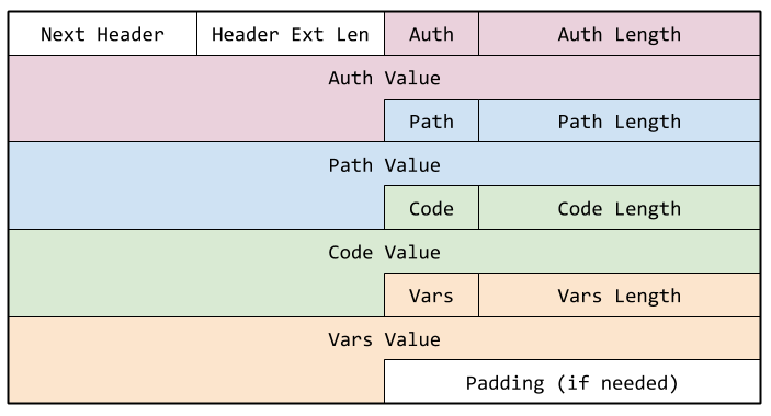
Fig. 52 Figure. Bayware IPv6 Extension Header
Execution Environment
The Execution Engine contains the elements to process the instructions inside the packets. It is composed of n individual processing units (PUs), where n is dependent on the particular switch product and its supported interfaces. Each PU is responsible for executing the instructions in a single packet.
Each PU in an engine consists of a sandbox for executing the microcode in a packet. The PU consists of a RISC-V ALU, a 32-deep register file (described below), and a data model implemented as collections of records.
The execution environment supports data records accessible in three types of data structures.
- Stand-alone record (SAR)
- includes the Switch Information Table, which is a single record of related information
- Direct-access records (DAR)
- includes the Connection Context Table, which is a collection of many different records, each describing an independent connection. Each record itself holds a series of data that describe the given connection.
- Indirect-access records (IAR)
- includes the Tag Lookup Table, which returns RCIs related to the tag when presented with a key. Such tables hold a collection of records. A given record is returned when presented with the associated key. These tables are hash-based.
PU offers the following tables:
| Table Name | Type | Description |
|---|---|---|
| Packet Meta Data | SAR | read-only access to pre-defined parsed packet data |
| Packet Program Data | SAR | read/write access to packet PRG_DATA chunk |
| Flow Program Data | SAR | read/write access to persistent data available to intra-flow packets |
| Topic Program Data | SAR | read/write access to persistent data available to inter-flow packets |
| Scratch Data | SAR | read/write access during program execution |
| Connection Context | DAR | read-only access to connection records |
| Switch Info | SAR | read-only access to switch information |
| Tag Lookup | IAR | key-value records that match tags to RCIs |
| Required Action Set | SAR | read/write access to records that define output action |
* Future versions will support user-defined Maps & Lists (both IAR type)
The following sections describe the PU and its instruction set in detail.
Programming Model
Supported RISC-V Architecture
The PU architecture and instruction set are based on the RISC-V open source ISA. The RV32IAC variant offers support for the base integer instructions, atomic instructions, and compressed 16-bit instructions.
A summary table follows this section that lists RISC-V instructions supported by the PU. Implementation priority will be given first to RV32I, then to A extension, and then to C extension. (The column at the right of the table indicates whether or not an instruction has been referenced in the current software documentation.)
RV32I Base Integer Instructions
As shown in the table, most 32-bit base integer instructions are supported (see below for unsupported instructions).
Keep in mind that RISC-V does no overflow checking for either addition or subtraction. This must be handled by the software itself, if required.
As well, mis-aligned LOADs and STOREs are not supported. That is, loads and stores must use naturally-aligned addresses: 32-bit accesses must use a 4-byte address; 16-bit accesses must use a 2-byte address; 8-bit accesses may use any address.
Atomic Instructions
The compound AMO instructions are supported. This allows software to perform a load, a binary transform, and a store on a given word using a single instruction i.e., a read-modify-write. Such instructions will always complete atomically.
Note that the AMO instructions allow atomic access to a single word only at any given time. In order to enforce exclusive access across multiple words, the software must employ semaphores. The RISC-V manual describes using the AMO.SWAP instruction to reserve multiple words as follows
li t0, 1                          # Initialize swap value.
    again:
        amoswap.w.aq t0, t0, (a0) # Attempt to acquire lock.
        bnez         t0, again    # Retry if held.
        # ...
        # Critical section.
        # ...
        amoswap.w.rl x0, x0, (a0) # Release lock by storing 0.
Only the topic program data allows multiple processors to access a shared bank of memory. Applications using topic program data may utilize a location within the topic program data memory as a shared semaphore in order to execute atomic instructions over multiple words within the memory.
Software may take advantage of the hardware read-modify-write capability for other memories even when there are no shared access considerations.
Compressed Instructions
As per the RISC-V manual, compressed instructions are first expanded into full 32-bit instructions before execution. Not all 32-bit instructions have a compressed counterpart. The PU supports all manner of commingled 16- and 32-bit instructions; 32-bit instructions may begin on any two-byte boundary.
Unsupported RISC-V Architecture
Unsupported Features
The Execution Environment’s PUs do not support RV32E, which is designed specifically for embedded systems by reducing the number of registers to 16. In Bayware’s engine, each PU supports 32 registers as described in Register File.
The Execution Environment’s PUs do not support RV64I. Each PU uses 32-bit registers (see Register File) and the address space uses 16 bits (see Memory Map).
Nor is there any support for integer multiplication or division (RV32M) or floating point operations (RV32D).
There is no stack. That is, instructions cannot save off variables to a LIFO-based structure during a function call. Nor can one function pass parameters to another function on a stack.
Likewise, there is no heap. Memory cannot be dynamically allocated.
There is no MMU. All memory uses physical addressing (including Instruction Memory) as described in Memory Map.
Unsupported Instructions
As indicated, the PUs in this Execution Environment support extensions I, A, and C from the RISC-V ISA. However, not all instructions are supported within each of these extensions. The following instructions are not supported:
from RV32I Base Integer Set
- FENCE
- CSR - control & status register functions
- ECALL
from RV32A Atomic Instruction Set
- LR
- SC
Load-Store Architecture
The PU operates using a basic RISC load-store architecture. This dictates that operands to the ALU must come from 1 of the 32 registers, R0 to R31, in the Register File or as an immediate passed from the instruction itself.
Data Sizes
A PU can operate on the following data sizes:
- Byte – 8-bit quantity
- Half Word – 16-bit quantity
- Word – 32-bit quantity
Register File
Each processing unit supports 32 32-bit registers for use by the instructions.
These registers are labeled x0 to x31 as per the RISC-V standard.
Note that x0 is hardcoded to 0–reads of this location always return 0 and writes to this location are ignored.
All other registers are fully readable and writeable by the instructions.
Registers x6 to x14 are initialized by hardware to non-zero values prior to processing each packet. All other registers are cleared to 0 prior to instruction execution. The initialization values are taken from the PU Page Registers, which contain base addresses for all PU-accessible memories.
Endian-ness
All PU addressing, as well as the entire NPU, operates as big-endian. This dictates that the most-significant data byte is written into the lowest-numbered address on word and half-word transactions. The following diagram illustrates this point.
A value of 0xAABBCCDD written to address 0x0 deposits data into memory as shown in the figure. A subsequent byte read access from address 0x0 returns 0xAA, the most-significant byte; a byte read from address 0x3 returns 0xDD, the least-significant byte.
Likewise, bits are numbered such that a more significant bit has a higher value than a lower significant bit. For instance, in the word shown above, the most-significant bit is labeled 31 and the least-significant bit is labeled as 0.

Fig. 53 Figure. Big-Endian Byte Ordering